Optional Accessories
Using the charger (BCX-1)
Two batteries can be inserted. It can also be used with only one battery inserted.
Charge the battery.
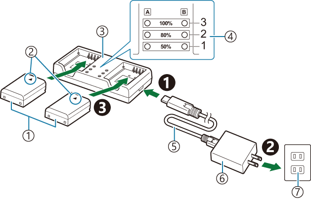
- Lithium ion battery (BLX-1)
- Direction indicating mark (J)
- Lithium-ion charger
- Charging indicators
- USB cable (CB-USB13: supplied)
- USB-AC adapter (F-7AC)
- AC wall outlet
Charging time is approximately 2 hours 30 minutes. See the table below for status of the charging indicators and battery charge.
Charging time does not change even when you charge two batteries at the same time.
Charging indicator Battery charge Indicator 1: Blinks Charging (less than 50%) Indicator 1: Lights up; Indicator 2: Blinks Charging (between 50% and 80%) Indicators 1 and 2: Light up; Indicator 3: Blinks Charging (between 80% and 100%) All indicators: Unlit Charging complete All indicators: Blinking Charging error
HLD-10 Power Battery Holder
An optional HLD-10 battery holder can be used to power the camera for extended periods.
- Make sure to turn the camera off when attaching and removing the holder.
Part names
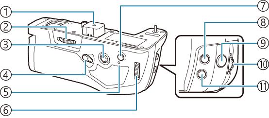
- Terminal cover
- Attachment wheel
- Multi selector
- Vertical shooting lock
- Battery charge lamp
- Rear dial
- AF-ON button
- F (Exposure compensation) button
- Shutter button
- Front dial
- ISO button
Attaching the holder
Remove the power battery holder (PBH) cover (a) on the bottom of the camera and the terminal cover (b) of HLD-10 before attaching the HLD-10. Once attached, make sure the HLD-10 removal knob is tightly secured. When not using the HLD-10, make sure to attach the power battery holder (PBH) cover to the camera and the terminal cover to the HLD-10.
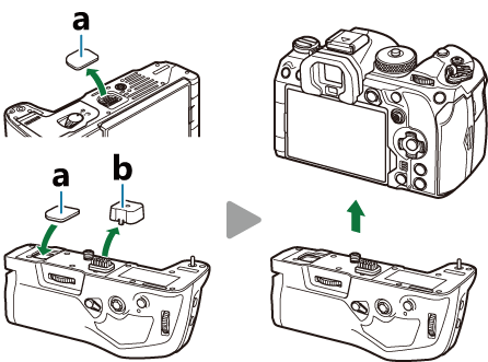
Store the Power battery holder (PBH) cover (a) in the HLD-10.
Inserting the battery
Use BLX-1 battery. Once you load the battery, make sure to lock the battery cover.
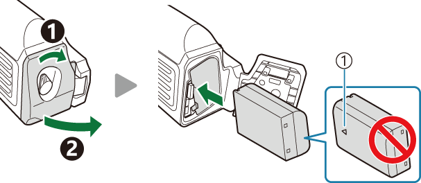
- Direction indicating mark
The monitor battery-level indicator (“Turning the camera on”) shows “PBH” when the camera is powered by the battery in the HLD-10.

Charging the battery in the power battery holder
To charge the battery in the power battery holder, load a battery in the holder and attach the holder to the camera; charge the battery in the same way as described in “Charging the Battery using the USB-AC adapter”.
The charge lamp of the holder lights during charging.
Using the buttons
Slide the vertical shooting lock of the HLD-10 in the direction of the arrow.
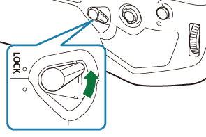
The roles performed by the F (Exposure compensation) button, ISO button and AF-ON button on the HLD-10 can be selected using the [Button Function] item. g “Changing the roles of buttons (Button Settings)”
- Buttons on the HLD-10 cannot be used when the vertical shooting lock is in the LOCK position.
Notes on using this product
- Use only the designated battery. Failure to do so could result in injury, damage to the product, and fire.
- Do not use your nail to turn the attachment wheel. Doing so could result in injury.
- Only use the camera within the guaranteed operating temperature range.
- Do not use or store the product in dusty or humid areas.
- Do not touch the electrical contacts.
- Use a dry, soft cloth to clean the terminals. Do not clean the product with a damp cloth, thinner, benzine, or any other organic solvents.
- Remove the batteries from the camera and power battery holder before putting the camera into storage for periods of a month or more. Leaving the batteries in the camera for extended periods shortens their lives, potentially rendering them unusable.
Designated External Flash Units
When using an optional flash unit designed for use with the camera, you can choose the flash mode using camera controls and take pictures with the flash. See the documentation provided with the flash unit for information on flash features and their use.
Choose a flash unit to suit your needs, taking into consideration such factors as the output required and whether the unit supports macro photography. Flash units designed to communicate with the camera support a variety of flash modes, including TTL auto and super FP. Flash units can be mounted on the camera hot shoe or connected using a cable (available separately) and flash bracket. The camera also supports these wireless flash control systems:
Radio-Controlled Flash Photography: CMD, ACMD, RCV, and X-RCV Modes
The camera controls one or more remote flash units by means of radio signals. The range of locations in which flash units can be placed increases. Flash units can control other compatible units or be fitted with radio commander/receivers to allow the use of units that do not otherwise support radio flash control.
Wireless Remote-Control Flash Photography: RC Mode
The camera controls one or more remote flash units by means of optical signals. The flash mode can be selected using camera controls (“Wireless remote control flash photography”).
Features Available with Compatible Flash Units
FL-700WR
| Flash control mode | TTL-AUTO, MANUAL, FP TTL AUTO, FP MANUAL, MULTI, RC, SL MANUAL |
|---|---|
| GN (Guide Number, ISO 100) | GN 42 (75/150 mm 1) GN 21 (12/24 mm 1) |
| Supported wireless systems | CMD, ACMD, RCV, X-RCV, RC |
FL-900R
| Flash control mode | TTL-AUTO, AUTO, MANUAL, FP TTL AUTO, FP MANUAL, MULTI, RC, SL AUTO, SL MANUAL |
|---|---|
| GN (Guide Number, ISO 100) | GN 58 (100/200 mm 1) GN 27 (12/24 mm 1) |
| Supported wireless systems | RC |
STF-8
| Flash control mode | TTL-AUTO, MANUAL, RC 2 |
|---|---|
| GN (Guide Number, ISO 100) | GN8.5 |
| Supported wireless systems | RC 2 |
FL-LM3
| Flash control mode | Varies with camera settings. |
|---|---|
| GN (Guide Number, ISO 100) | GN 9.1 (12/24 mm 1) |
| Supported wireless systems | RC 2 |
Maximum lens focal length at which the unit can provide flash coverage (figures following slashes are 35 mm format equivalent focal lengths).
Functions as commander (transmitter) only.
Wireless remote control flash photography

Wireless flash photography is available with compatible flash units that support wireless remote control (RC). The remote flash units are controlled via a unit mounted on the camera hot shoe. Settings can be adjusted separately for the units in up to three other groups.
RC mode must be enabled on both the master and remote flash units (“Designated External Flash Units”).
Configuring RC mode
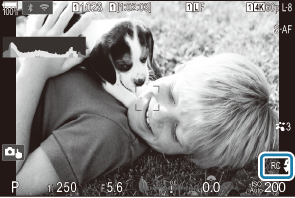
Select [On] for [A RC Mode] and press the OK button.
- The camera will exit to the shooting display.
”RC” appears on the screen.
Press the OK button.
The RC mode super control panel will be displayed.
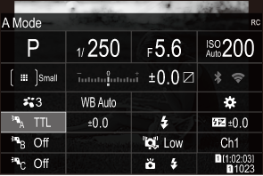
- The standard LV super control panel can be displayed by pressing the INFO button. The display will change each time the INFO button is pressed.
Adjust flash settings.
Highlight items using the FGHI buttons and rotate the front dial to choose settings.
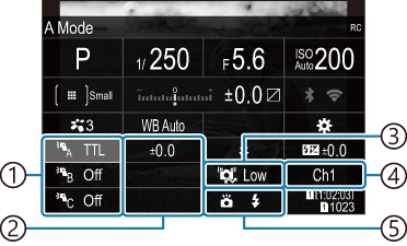
- Group, flash control mode
- Flash compensation
- Optical signal strength
- Channel
- Flash mode
Group Choose a group. Changes to settings apply to all units in the selected group. The unit mounted on the camera works as a member of Group A. Flash control mode Choose a flash mode. Flash compensation Adjust flash output. When [Manual] is selected for flash mode, you can choose a value for manual flash output. Optical signal strength Choose the brightness of the optical control signals emitted by the flash units. Choose [High] if you have placed flash units close to the maximum distance from the camera. This setting applies to all groups. Flash mode/output Choose A (standard) or FP (super FP). Choose super FP for shutter speeds faster than the flash sync speed. This setting applies to all groups. Channel Choose the channel used for flash control. Change the channel if you find that other light sources in the area are interfering with remote flash control. Set the unit mounted on the camera to [TTL AUTO].
- Flash control settings for the FL-LM3 can only be adjusted using the camera.
Setting up the flash
Set the remote flash units to RC mode.
- Turn the external flash units on, press the MODE button, and select RC mode.
- Set up the group to control with the dedicated external flash and configure their communication channels so that they match the camera settings.
Arrange the flash units.
- Position the wireless units with the remote sensors facing the camera.
- Take pictures after confirming that the camera and flash units are charged.
Wireless Flash Control Range
The illustration is intended as a guide only. The flash control range varies with the type of flash mounted on the camera and the conditions in the surrounding area.
Flash Control Range for Camera-Mounted FL-LM3 Flash Units
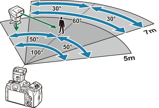
- We recommend that each group contain no more than 3 flash units.
- Wireless flash photography is not available in anti-shock mode or in rear-curtain slow sync mode when a shutter speed slower than 4 s is selected.
- Waiting times longer than 4 s cannot be selected in anti-shock and silent modes.
- Flash control signals may interfere with exposure if the subject is too close to the camera. This can be mitigated by reducing the brightness of the camera flash, for example by using a diffuser.
Other external flash units
Third-party flash units can be mounted on the hot shoe or connected via a sync cable. Be sure to replace the cap on the external flash connector when it is not in use.
Note the following when using a third-party flash unit mounted on the camera hot shoe:
- Using obsolete flash units that apply currents of more than about 250 V to the X-contact will damage the camera.
- Connecting flash units with signal contacts that do not conform to our specifications may damage the camera.
- Select mode M, choose a shutter speed no faster than the flash sync speed, and set [KISO] to a setting other than [Auto].
- Flash control can only be performed by manually setting the flash to the ISO sensitivity and aperture values selected with the camera. Flash brightness can be adjusted by adjusting either ISO sensitivity or aperture.
- Use a flash with an angle of illumination suited to the lens. Angle of illumination is usually expressed using 35-mm format equivalent focal lengths.
Principal Accessories
Converter lenses
Converter lenses attach to the camera lens for quick and easy fish-eye or macro photography. See our website for information on the lenses that can be used.
Eyecup (EP-18)
Removal
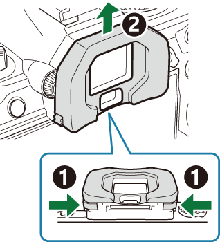
Push both levers inward and lift the eyecup.
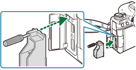
Cable Clip (CC-1) / Cable Protector (CP-2)
When attaching the USB cable, using an optional cable protector and cable clip helps prevent damage to the connectors and disconnection of the table.
Mount the cable protector on the camera.
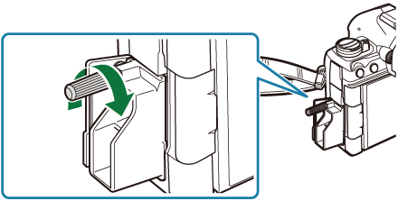
Tighten the screw.
Clip the cable clip to the cable and attach the clip to the strap.
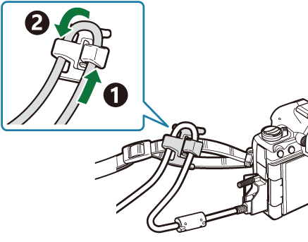
- The clip attaches to the buckle.